Laser Scanning Systems - study material
| Site: | E-learning.ks.org.mk |
| Course: | BIM skills: Effective Data Collection for Digitization of Existing Assets |
| Book: | Laser Scanning Systems - study material |
| Printed by: | Guest user |
| Date: | Saturday, 26 April 2025, 6:42 AM |
1. Functional Principle of Laser Scanning Systems
Laser scanning systems enable the contactless determination of 3D coordinates of points located on the surface of the measured object. The scanning result is an irregular raster so-called point cloud, which documents the measured object. The point cloud is used as a base for the creation of a spatial model of the measured object or as a technical base for verification of geometrical parameters or for deformation analysis.
Laser scanning belongs among non-selective measuring methods; it means that measured points are located non-selectively in a raster, which is defined by regular angular distances in the horizontal and vertical direction. In contrast with conventional surveying methods, coordinates of characteristic points are obtained by modeling or by generalization of the main features of the created 3D models or the resulting point cloud (Fig. 1).
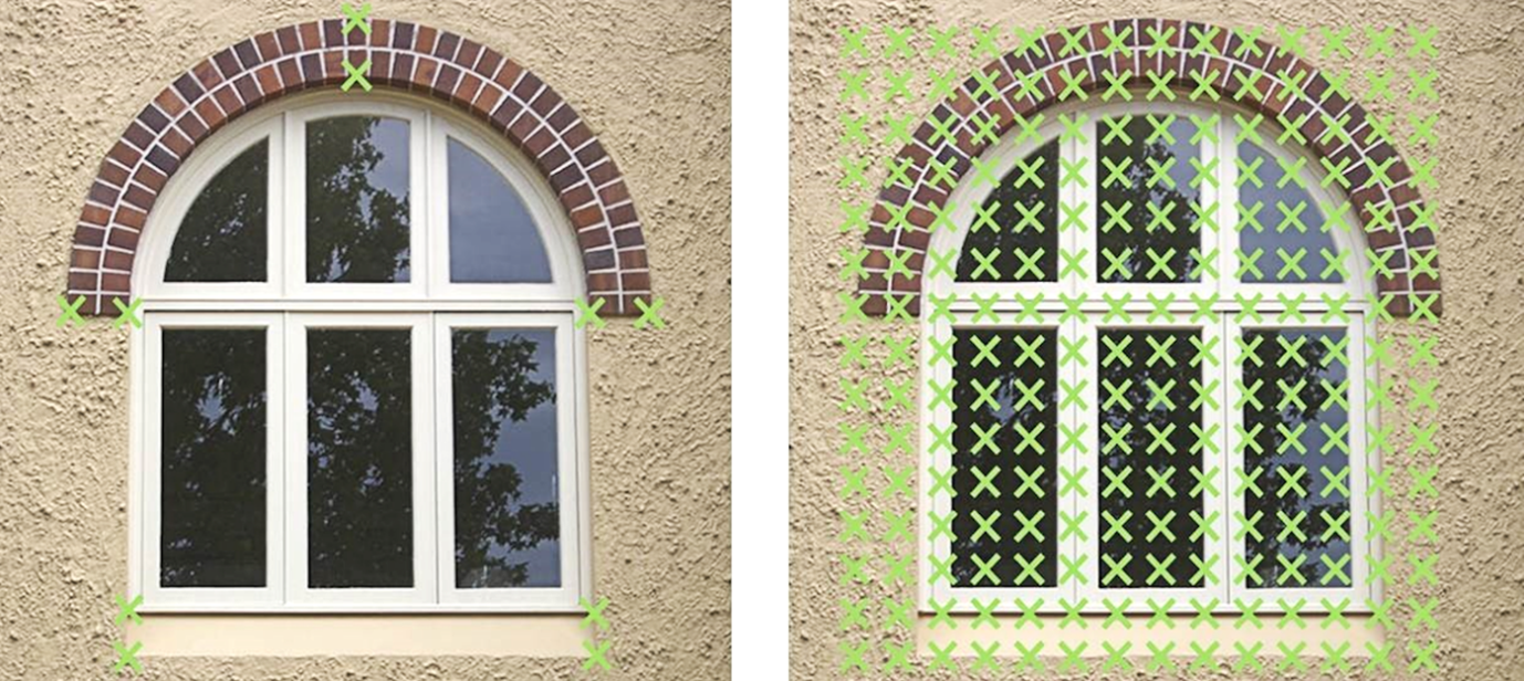
Figure 1 Difference between selective (left) and non-selective method (right)
For the effective use of laser scanning and data obtained by laser scanning, it is necessary to know the basic functional principles of these systems. Laser scanners like other measurement systems have their own physical, functional, as well as technological limitations, which have to be taken into account during the preparation of measurement as well as during data processing. Otherwise, they can cause a devaluation of results even when the measurement was correct.
Optical 3D measurement techniques use the method of triangulation or polar method to determine the spatial position, whereby they utilize characteristics of electromagnetic wave propagation in the environment. Systems using the triangulation principle can be passive, based on the processing of images or active using projection of various light marks and textures on the surface of the measured object. In the systems using the polar method, the measured distance is determined by pulse measurement (time-of-flight), phase measurement, frequency measurement, or interferometric measurement (Beraldin et al. 2010). Classification of 3D optical measuring systems according to the determination of the spatial position of measured points is represented in Fig. 2.
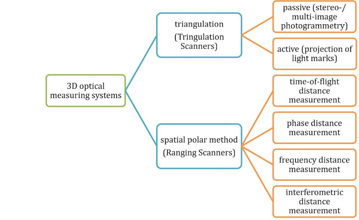
Figure 2 Classification of 3D optical measuring systems
The position of a measured point, in the systems, using spatial triangulation, is determined on the base of image processing with known sensor geometry of the scanning system (Luhmann 2006). In most cases, these are active triangulation scanners where at the one end of a baseline a source of emission (light) is located, which projects light (measuring) marks or structured light on the surface of measured object and at the opposite end of the baseline, there is a camera (CCD, CMOS) scanning the position of the projected target. In most cases for creation of the 3D model of the measured object, it is necessary to signalize reference points on the surface of the measured object (to determine the interior and exterior orientation). Triangulation scanning systems have short range (up to several meters in most cases) and higher accuracy about several hundredths of millimeters.
Nowadays the majority of laser scanners with the range longer than 10 m use the principle of the spatial polar method. The 3D point position by these scanner systems is calculated from the measured horizontal direction (from a calculated horizontal angle ω), zenith angle ζ, and slope distance d (Fig. 3).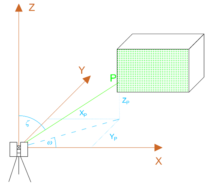
Figure 3 Determination of a point position by the polar method
2. Categorization of Laser Scanners
Scanning systems could be categorized according to various criteria. Depending on the placement, scanners are divided into terrestrial or airborne (aerial). If the scanner is placed on the Earth’s surface (or close to the Earth’s surface) or on a vehicle moving on the Earth’s surface (a car, a train, a robot arm, etc.), it is a terrestrial laser scanner. If the instrument is placed on an aerial vehicle (airplane, helicopter, UAV), it is an airborne laser scanning system.
Terrestrial systems are further divided into static and kinematic, depending on whether they are placed stationary or on a moving vehicle (car, trolley, carriage, etc.). The most frequent realization of the kinematic laser scanning system is a so-called mobile mapping system located on vehicles (Fig. 4a) or a scanning system in the form of a railway track geometry measuring trolley (Fig. 4b). Kinematic systems placed on vehicles are used mainly for scanning of roads and their infrastructure and streets. Scanning trolleys are mainly used for documentation of rail corridors, railway track scanning including all equipment that belongs to the railway as well as for as-built documentation railway tunnels, etc.
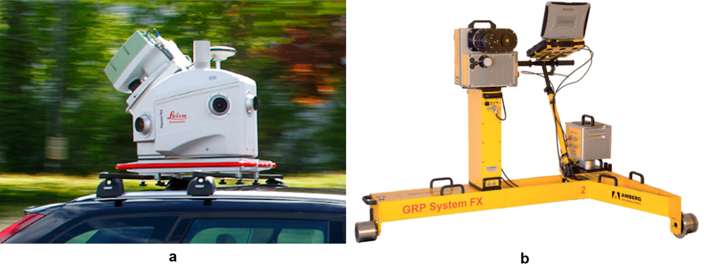
Figure 4 Kinematic terrestrial laser scanning systems: a) Leica Pegasus mobile maping system (Leica Geosystems, 2019) and b) Amberg Rail Clearance IMS 5000 (Amberg Technologies, 2018)
The next criterion for the categorization of laser scanners is the field of view and scanning range. According to that, scanners can be divided into cameras, panoramic, and hybrid scanners (Fig. 5). In the case of camera scanners, the laser beam is deflected (to points of a raster) by oscillating mirrors or prisms what enable the deflection of the laser beam into a relatively small field of view. Panoramic laser scanners use rotating prisms or rotating mirrors as projection mechanisms. The laser beam is deflected in the vertical direction only with minimal limitation (under the instrument), while the deflection in the horizontal direction is realized by the rotation of the scanner around its vertical axis. The hybrid system is a combination of the panoramic and camera scanner system. These scanners are able to scan 360° in the horizontal direction with a significantly limited field of view in the vertical direction. An oscillating mirror in combination with rotation around the vertical axis of the instrument is used as a projection mechanism.
Another important property of scanners is the scan rate (speed of scanning) expressed by the number of measured points per second. Present scanners with short and middle range enable to measure several 100,000 points per a second (up to two million points per second). Scanners with long range generally have lower scan rate, which reaches several 10,000 up to 100,000 points per second. It is necessary to point out that the abovementioned classification of laser scanners is based on the present instruments offered which, however, develop over the time, therefore the categorization of the terrestrial laser scanning systems may change over the time (especially the scan rate of long-range instruments increases).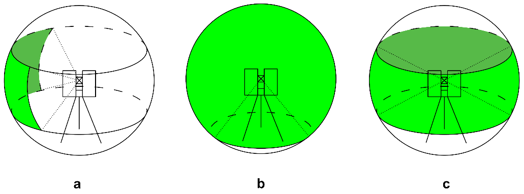
Figure 5 Categorization of TLS according to the field of view: (a) camera scanner, (b) panoramic scanner, and (c) hybrid scanner
3. Measurement Using Terrestrial Laser Scanners
The procedure of data acquisition and creation of models using TLS can be divided into three main steps. The first step is the preparation for measurement. It involves reconnaissance of the measured object, choosing stations for scanning, and signalization and, if necessary, determination of coordinates of reference points. The second step is the procedure of scanning (data acquisition). The third last step is the verification of the results in the field (Kopáčik et.al., 2020).3.1. Preparation for measurement
During the reconnaissance, the surface and the shape of the scanned object and its structural elements are detected. Based on the information obtained about the object, the configuration of scanner stations and reference points are planned with respect to the type and characteristics of the scanner used such as range, the field of view, and accuracy.
If it is not possible to scan the measured object from a single station, it is often necessary to choose reference points in the scanning site. The reference points are then used to merge several different point clouds into one common coordinate system. They can be signalized naturally directly on the measured object (e.g., sharp edge, spherical shapes, or its parts), or they can be signalized artificially using targets. The majority of scanning systems use a particular type of target for reference points which are automatically recognized by the scanning system. They may be plane or spherical, alternatively hemispherical targets. After scanning of spherical targets, a sphere is fitted to the points lying on the surface of the target and its estimated center is used as a reference point. Other types of targets are plane targets with a retroreflective surface, which are recognized by the scanning system based on the high intensity of the reflected measuring signal or targets with high contrast between parts of the target (so-called checkerboard targets). In Fig. 6 there are some of the target types used for signalization of reference points – target Leica HDS (on the left), checkerboard target (in the middle), and spherical target (on the right).
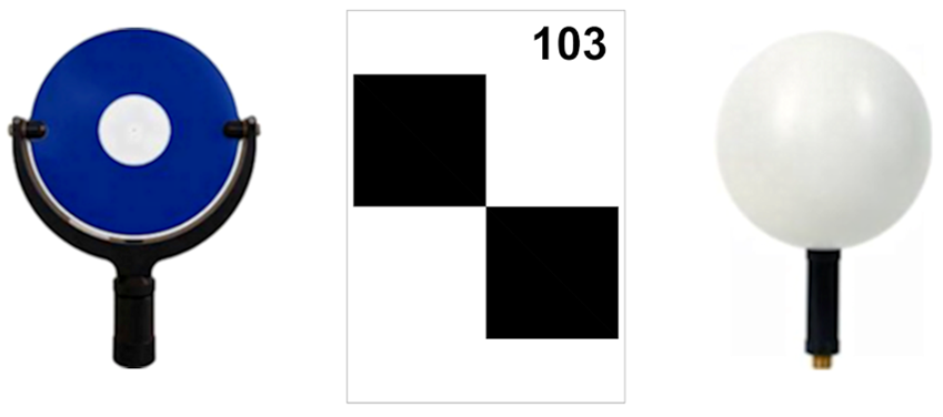
Figure 6 Examples of reference points
In many cases, it is necessary to create the 3D model of the measured objects in a given coordinate system (local coordinate system of the measured object or national coordinate system). The coordinates of selected reference points have to be determined in the given coordinate system by other conventional surveying methods. The results of scanning are transformed based on these points into the defined coordinate system using spatial transformation.
An integral part of the preparation works is planning and implementation of occupational safety and health protection as well as the protection of instruments and equipment during the measurement. This is important mainly in industrial factories because the measurements are often realized during the full operation of objects. When choosing an instrument, it is necessary to consider the environmental conditions in which the measurements are realized, they can extremely differ from the conditions in other environments, e.g., urban areas. The instrument has to be often protected against extreme dust and humidity. Measurements are often realized in a chemically aggressive environment what significantly influences the form of stabilization of reference points (using a normal metal anchorage is not possible), or the measurements are realized in explosive conditions (instruments need certificate for explosive conditions).3.2. Scanning
Scanning means the procedure of the determination of spatial coordinates of points, which are lying on the surface of the measured object. It is also possible to obtain radiometric information (color) about the measured object during the scanning. This information is the intensity of the reflected measuring signal or colors (textures) from the images captured by digital cameras often embedded in the scanning system.
Scanning consists of the definition of scanning parameters and of starting the scanning procedure. The scanning parameters define the area and the density of the scanned points on the surface of the scanned object. Laser scanners, which are equipped with a digital camera, enable us to define the scanning area directly on the digital image in the shape of a spherical rectangle. For most scanners, it is possible to define a scanning area also by starting and ending horizontal direction and zenith angle. The next important parameter is the scanning density (resolution) because this parameter influences the detail of measurement and consequently the amount of the data obtained by scanning. The resolution can be set by the definition of the angular difference between two consecutive points and profiles, it means by definition of the step for the horizontal and vertical angle Δω, Δζ, or by definition of raster parameters in a certain distance from the scanner, e.g., 3 mm × 3 mm per 50 m. To simplify the control of the instrument, some producers limited the possibility to set the scanning parameters only to define the scanning area and to choose the scan resolution from some predefined resolutions. The resolution in these systems is mainly defined as a number of points per 360° in the horizontal and vertical direction, e.g., 40,960 points per 360°, which represents 1.5 mm x 1.5 mm per 10 m, eve. 7.7 mm × 7.7 mm per 50 m.
After starting the measurement, scanning is performed automatically without any necessary intervention of the user. The scanning procedure is controlled by a control unit embedded in the instrument or by an external computer. The scanner determines the spatial coordinates of points and saves them into the internal memory of the instrument or into the control PC. In addition to coordinates, radiometric information is obtained during the measurement. This information is the intensity of the reflected measuring signal or color from the images captured by a digital camera. The measuring signal is reflected off the measured object with various intensities that depend on the physical characteristics of the scanned surface (material, color, roughness). On the base of the radiometric information, it is possible to assign a color to measured points (Fig. 7).
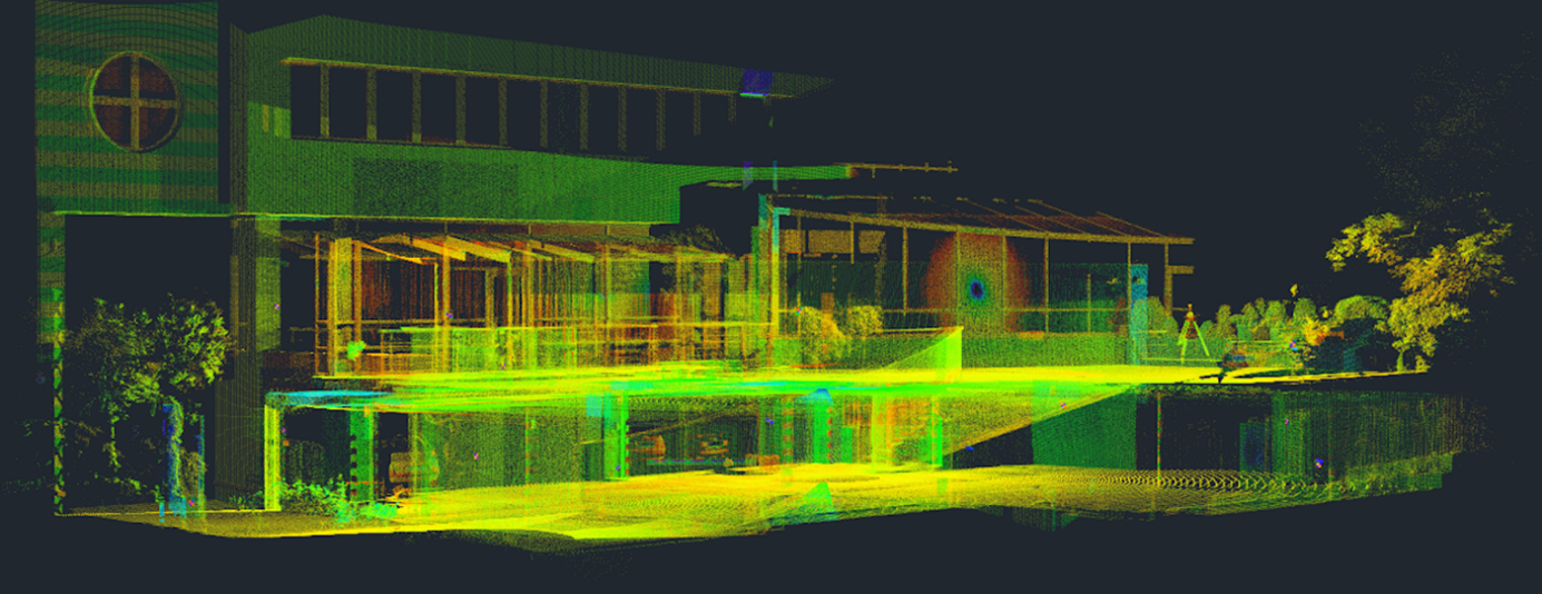
Figure 7 Result of scanning – point cloud (colored according to intensity)
The results of the scanning procedure are point clouds in coordinate systems of the scanner at particular stations and the above mentioned radiometric information.
4. References
Amberg Technologies. (2018). Amberg clearance IMS 5000. https://ambergtechnolo-gies.com/fileadmin/user_upload/amberg-echnologies/downloads/Rail/Clearan-ce_IMS5000_Datasheet_en.pdf. ; Accessed 16 Dec 2019.
Beraldin, J. A., et al. (2010). Laser scanning technology. In G. Vosselman & H. G. Maas (Eds.), Airborne and terrestrial laser scanning (pp. 1–42). Dunbeath: Whittles Publishing.
Kopáčik, A. et al. (2020). Engineering surveys for industry. Cham: Springer Nature Switzerland.
Leica Geosystems. (2019). Leica Pegasus: Two mobile sensor platform. https://leica-geosystems.com/kk-kz/products/mobile-sensor-platforms/capture-platforms/leica-pegasus_two. Accessed 16 Dec 2019.