Laser Scanning Systems - study material
1. Functional Principle of Laser Scanning Systems
Laser scanning systems enable the contactless determination of 3D coordinates of points located on the surface of the measured object. The scanning result is an irregular raster so-called point cloud, which documents the measured object. The point cloud is used as a base for the creation of a spatial model of the measured object or as a technical base for verification of geometrical parameters or for deformation analysis.
Laser scanning belongs among non-selective measuring methods; it means that measured points are located non-selectively in a raster, which is defined by regular angular distances in the horizontal and vertical direction. In contrast with conventional surveying methods, coordinates of characteristic points are obtained by modeling or by generalization of the main features of the created 3D models or the resulting point cloud (Fig. 1).

Figure 1 Difference between selective (left) and non-selective method (right)
For the effective use of laser scanning and data obtained by laser scanning, it is necessary to know the basic functional principles of these systems. Laser scanners like other measurement systems have their own physical, functional, as well as technological limitations, which have to be taken into account during the preparation of measurement as well as during data processing. Otherwise, they can cause a devaluation of results even when the measurement was correct.
Optical 3D measurement techniques use the method of triangulation or polar method to determine the spatial position, whereby they utilize characteristics of electromagnetic wave propagation in the environment. Systems using the triangulation principle can be passive, based on the processing of images or active using projection of various light marks and textures on the surface of the measured object. In the systems using the polar method, the measured distance is determined by pulse measurement (time-of-flight), phase measurement, frequency measurement, or interferometric measurement (Beraldin et al. 2010). Classification of 3D optical measuring systems according to the determination of the spatial position of measured points is represented in Fig. 2.
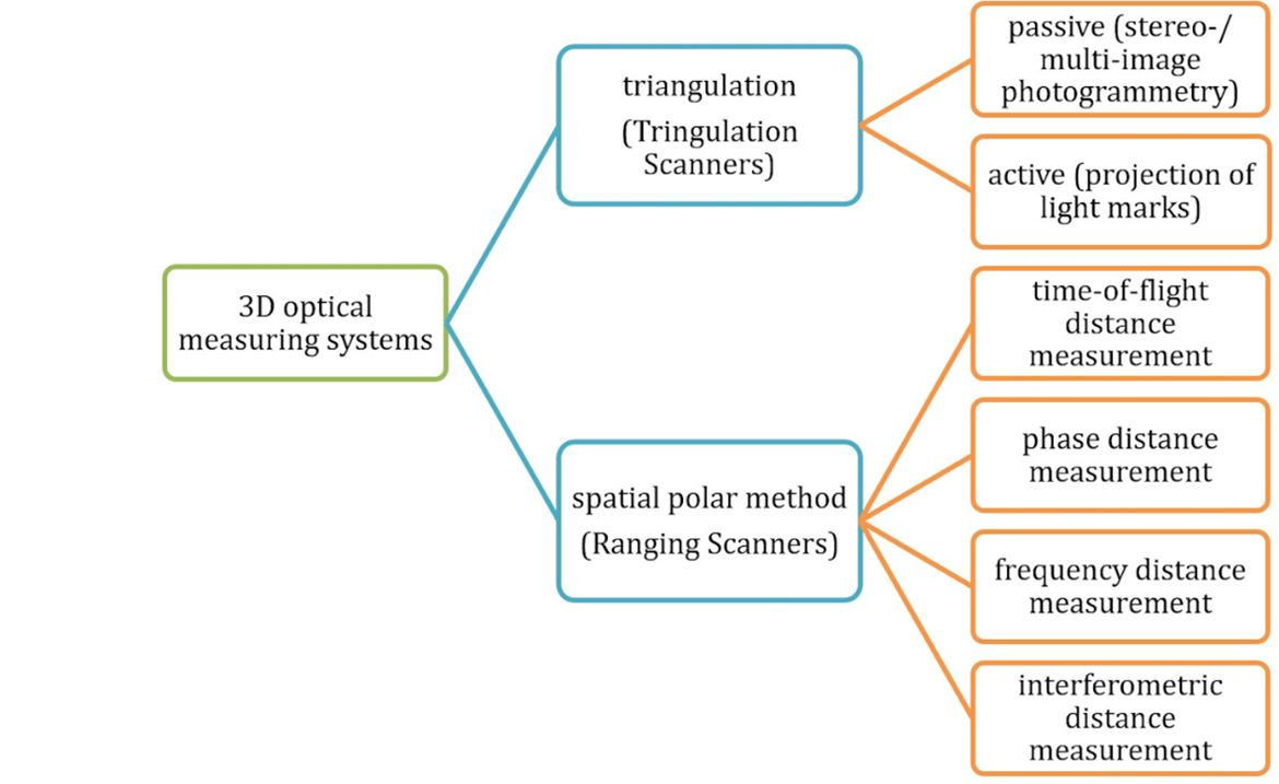
Figure 2 Classification of 3D optical measuring systems
The position of a measured point, in the systems, using spatial triangulation, is determined on the base of image processing with known sensor geometry of the scanning system (Luhmann 2006). In most cases, these are active triangulation scanners where at the one end of a baseline a source of emission (light) is located, which projects light (measuring) marks or structured light on the surface of measured object and at the opposite end of the baseline, there is a camera (CCD, CMOS) scanning the position of the projected target. In most cases for creation of the 3D model of the measured object, it is necessary to signalize reference points on the surface of the measured object (to determine the interior and exterior orientation). Triangulation scanning systems have short range (up to several meters in most cases) and higher accuracy about several hundredths of millimeters.
Nowadays the majority of laser scanners with the range longer than 10 m use the principle of the spatial polar method. The 3D point position by these scanner systems is calculated from the measured horizontal direction (from a calculated horizontal angle ω), zenith angle ζ, and slope distance d (Fig. 3).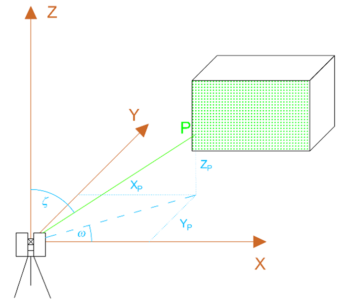
Figure 3 Determination of a point position by the polar method